About three years ago, from the time I’m writing this, I started a project to make an ambilight and give my home entertainment system some more pizzazz. Ambilight is actually a term used by some (or one) TV manufacturers to describe the technology they put into some of their television products. It’s short for ambient light, as you might expect.
I was inspired to build my own ambilight by a conflux of two interests: programmable LED lights, having seen a coworker’s talk on his TIE Fighter Art car for the Burning Man festival; and a desire to learn more about electronics and soldering. At first I didn’t really know what I wanted to make, so I just started doing some research on the Internet. My research led me to a blog post from Tested, which described making a type of ambilight. It had a few pre-set color schemes and animations, all programmed on an Arduino. Of course, I wanted to be fancier. I wanted the backlight to match the colors on the display.
The following is the story of how I made my own ambilight - the problems I had to solve, triumphs I basked in, and the many, many, many points of failure along the way. Sit back, relax, and enjoy!
Humble Beginnings
My first step was to learn how to work with the materials and get a programmable LED strip working at all. So:
- One Arduino
- Soldering Iron
- Solder
- Hook-up wire
- Two meters of programmable LEDs
- Power adapters
- Barrel jack switches
- and alligator clips
later, and I had everything I needed for version 0.1. The total cost at this point was around 170 USD, with the majority of that being the soldering iron. If you already have one of those, the cost at this point would be about 70 USD. Arduino is great because it’s rather well documented when you’re getting started. I recommend the guide over at arduino.cc. Very quickly I had version 0.1, which was a poor-man’s ambilight. It displayed exactly one color: a softened white. It was neat, but not anywhere near peak-awesome.
So, work on an official version 1.0 started almost immediately. I set out with two goals:
- The colors of the LEDs needed to mimic the colors from the edges of the picture, so that the light surrounding the TV is an extension of what’s on screen.
- The lights needed to be responsive.
I estimated that at 15 frames per second, lag in the light would be imperceptible to a human observer focused on the screen itself, so the target time to capture and analyze a frame and push the results to the LEDs was 66.7ms. However, the first hurdle I faced was that the Arduino didn’t have nearly the processing power - or even the capability - to receive and analyze an HDMI signal.
Life of Pi
Enter the Raspberry Pi. I essentially took two steps backward here after having taken one step forward with version 0.1. I had learned a lot already about assembling small electronics using the Arduino, but didn’t know how to work with a Raspberry Pi. On top of that, the strip was Arduino-ready; along with it came the Arduino C library for its driver type, LPD8806. No official library for this type of strip exists for the Raspberry Pi. So in addition to getting up and running on a Pi, I would have to figured out how to control the strip all over again. There were several unknowns at this point:
- GPIO (General Purpose Input/Output) on the Pi, in order to control the LED strip
- A program for LED control
- HDCP encryption on the HDMI signal
- HDMI capture
My strategy was a basic divide-and-conquer; solve each one individually and piece everything together. I started with GPIO.
GPIO-h No
Fortunately a lot of documentation exists for getting a Pi up and running, just not for all the other things I wanted to do with it. In contrast, attempting to control the LEDs with the Pi was a bit of a disaster at first. I tried three things:
- Port the Arduino library myself using Python GPIO control. Didn’t work.
- Use LPD8806.py. Someone already wrote it. No effect on the strip.
- Use Bibliopixel, a more robust library that someone else had already written. No effect on the strip.
The latter two libraries made use of SPI, which stands for Serial Peripheral Interface. It is an interface bus used to send data between micro-controllers and small peripherals. In particular, there are three important components that were most relevant to my project: the MOSI (Master Out/Slave In) pin, the MISO (Master In/Slave Out) pin, and the CLK (clock) pin. A little bit of digging into SPI on a Pi revealed my first problem.
Turns out you need to enable SPI on the Pi before you can use it.

Now, it also happens that there’s a program available which tests SPI by using a short-circuit between the MOSI and MISO pins. With a jumber cable connecting them, the program writes to the former and simultaneously reads from the latter. Funny enough, this didn’t work on the Pi I had. I spent a full night digging into OS options, conducting research, and fiddling with blacklists and other tests. Eventually I convinced myself that my Pi was busted, so I ordered a new one.
The new Pi worked great. Later on I discovered that the jumper cables I was using did not make the most reliable contact with the pins, so it might have just been imperfect contact appearing to make the Pi not work. Oh well… onward!
How Did-I-Get Myself Into (This)?
The next step was capturing the HDMI video stream in a form which I could read it frame-by-frame. This took literally forever to get started because the capture device I found online and ordered was some sketchy thing from Malaysia. And being a sketchy device from Malaysia, it was just that… sketchy. For example, the product I ordered was “EasyCap,” and the product I received was labeled “EasierCap.” Cool, maybe it’ll be easier?
It immediately didn’t work.
…because the USB cable it shipped with didn’t actually carry enough power to power it. Well done… whatever sketchy company I ordered it from.
Once I actually powered the device, I used a program distributed with Linux/Rasbian called mplayer to visualize the /dev/video0 feed, which is what the capture device would write to. Unfortunately all I got at first was a monochrome-green screen. I had two suspicions up-front: either the Pi still couldn’t route enough power to the device for it to work properly, or mplayer was configured incorrectly.
I figured it would be prudent to try the capture device on Windows, where it was supposed to be supported using the software that came on the disk with it. Fortunately, it worked. I was able to get my N64 hooked up to it and could play Mario Tennis through the capture device, viewing it on my PC. “Why the N64?” you might ask. “Why not?” I would answer. Also, the capture device takes three-channel RCA, so I might as well have some fun with it. So, why was the Raspberry Pi failing to display the video?
I dove deeper into the documentation for mplayer to try to find options that would make sense for my setup. It was probably my most sophisticated use of man pages ever. I eventually stumbled upon the rawvideo option, which ended up displaying the video somewhat correctly. After a few failed attempts at mixing command options…
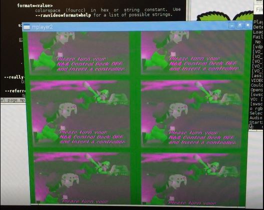
…I proved that the capture device was working and writing to /dev/video0. The other good news was that the device seemed to get around HDCP encryption1. Somehow. I don’t feel like asking a lot of questions here. In case you’re wondering, the working command line for mplayer was:
1 | mplayer /dev/video0 --demuxer=rawvideo --rawvideo=format=rgba:w=720:h=576 |
This progress was good enough for me to consider moving on to the next component: how do I analyze the picture? Some cursory searches for image and video processing led me to OpenCV. Even better, OpenCV has Python bindings. I was still sticking to the goal of writing this software in Python for ease of coding, figuring that it would perform just fine2. The bad news was that I had to download and compile OpenCV from source, and it literally took an entire day – 24 hours – to compile on the Pi. Very quickly I had a program that could read from /dev/video0 and output the stream to a simple window.
1 - I do not condone illegal copying of copyright protected digital content.
2 - This is what we like to call ‘foreshadowing.’
Performance Critical
This is where I ran into more failure. Python is slow. Computer vision is really slow. The Raspberry Pi isn’t exactly the most powerful computer in the world. The program just to read and display back the video signal ran at a blisteringly slow two frames per second. At least if I didn’t actually display the image, it would jump to 5 frames per second! This was still a far cry from my target 15 frames per second. This prompted a switch of my target language to C++. I quickly converted my Python program to C++, and that version of the program ran at 23 frames per second. This was much more promising, but it also meant that I could no longer utilize the existing Python library for controlling the LED strip, and I’d have to roll my own in C++.
The Part Where I Go Insane
And then I encountered the single most confusing bug in the entire project. I set out writing a simple LED class which would store an array of colors and write it out to SPI using the same protocol that the Python library did. I could compile this class into a library and link that into another program to drive the whole ambilight. I borrowed the SPI test program to perform this write of the data. That program was known to work. Mine didn’t. So I put on my engineering hat and started to narrow down the problem:
- Write the LED library, link it into a separate main program. Didn’t work.
- Implement SPI directly in main(). Works.
- Move contents of main() into SPI library, and call from main(). Didn’t work.
- Use a global function from SPI library instead of a class, call from main(). Works.
- Call the global function from the LED library class. Works… sometimes??

I was beyond confused, especially at the last troubleshooting configuration when the behavior would change without any external influences. Eventually, I happened to notice that the observed behavior would change when I added printfs for debugging. Yup, I was at that point. The behavior also changed when moving around a for loop that was setting some values in a fixed-size array that was part of the LED class. These bits of information led me to my answer: the stack. The SPI structure I was creating to send was being allocated on the stack, and its alignment mattered (well, sort of). I confirmed this by creating dummy arrays on the stack just before creating the SPI structure, and that could control whether or not the SPI send succeeded or failed. Then I actually went and read the documentation for the SPI library:
1 | * Zero-initialize the structure, including currently unused fields, to |
Well… shit. Lesson learned. Always read documentation. You never know when it might spare you from insanity.
Analyze This… Frame
At this point, I could go back to writing a program to analyze a video frame, and this time I’d be writing in C++. I started with a standalone program that would read an image file and run the algorithm I intended to use on the video stream. It was pretty straightforward: given an image, split the left, right, and top edges into equally-sized boxes - one box for each LED along that edge. Take a histogram of the RGB values within each box. Take the most frequent value from each channel, and those are the final RGB values for the box, or LED. The algorithm at work looks like this:
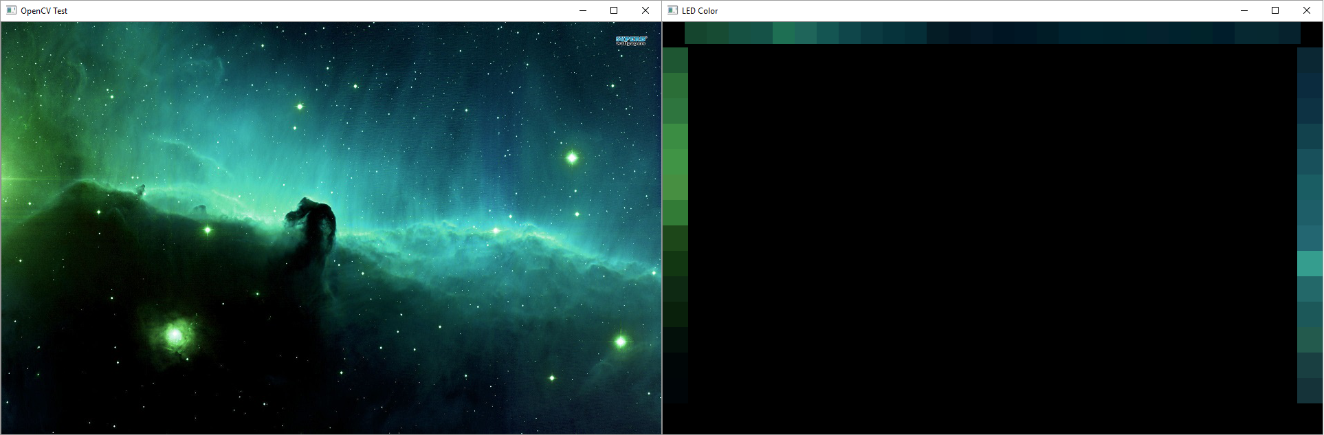
I also leveraged this standalone program to profile the algorithm. It revealed a quirk, albeit one I could work with - the first OpenCV operation on the image would take >500ms, but subsequent operations would be sub-millisecond, even repeats of the first. I attribute this to either allocation or caching that OpenCV is performing behind the scenes. Technically I could go find out since I have the source. Anyway, entire frame analysis took about 32ms. But this test was being run on my PC which was much beefier than the Pi, so it was promising but I couldn’t get too excited yet. I ported the code over to the Pi and measured it at 40ms; not as bad as I thought but combined with the time it took the Pi to decode a video frame it was still 17ms slower than my target. Before I moved onto optimization I wanted to start putting all the pieces together.
(Trying to) Put It All Together
The first thing I set up was a really simple test case: Mario Tennis, again. I rigged the program to output the histogram to a single strip of LEDs, and basked in the glory of success.
It looked like it was holding up so I moved onto more difficult test cases like full frames from my TV. Then I ran into real trouble. The Pi wasn’t fast enough to decode larger frames in order at a consistent rate, and the decoded frames would jump between past and present. You can see the effect it had on the lights in the video below; some really horrible flickering particularly whenever the scene color changes dramatically. I tried everything I could think of to speed up any component of the program, but to no avail. The problem wasn’t even the time to analyze a frame, like I thought it might be earlier on. The real problem was that the Pi 2 I had was not powerful enough to handle the full video stream. At this point the project was in serious jeopardy.
I had two ways to move forward: try upgrading to a Raspberry Pi 3, or try to blend successive frames together over time to smooth out the noise created by the frames jumping. While this seemed like a great idea on paper, and looked good when previewing the blended frames in the test program, the results with the lights were still not as good.
Now about the Raspberry Pi 3. When it arrived, it basically saved the project. The performance boost from the newer model was exactly what I needed to pull the whole thing together. It was basically a miracle. The responsiveness and smoothness almost immediately fell within the specificiations I had set out with, and version 1.0 was almost complete.
The last bits were minor - I needed a way to start the software when the Pi booted, because I wouldn’t have a keyboard, mouse, or display hooked up to the Pi at all times to run the program myself. It’s pretty easy to do this with Linux. You write a script for the service, let’s call it ambilight, and place it in /etc/init.d, then use the following command to specify that that script should run on startup:
1 | sudo update-rc.d ambilight defaults |
Lastly I needed to finalize the wiring behind the TV. It’s somewhat extensive:
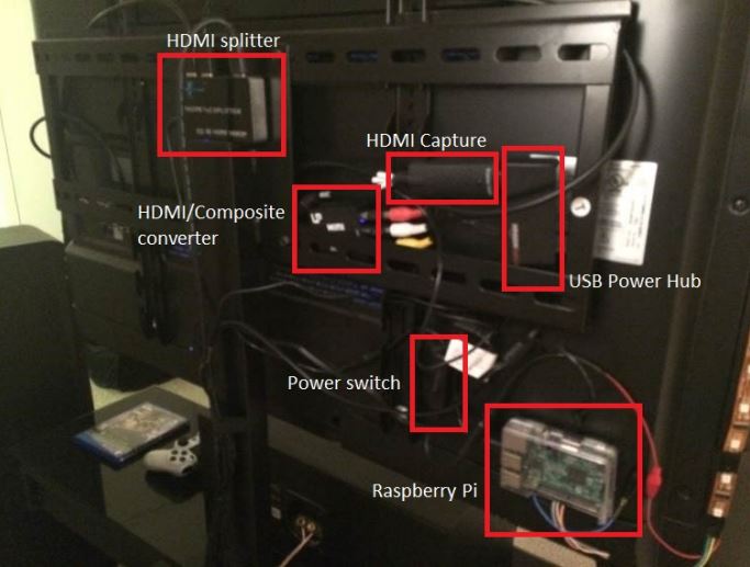
So here’s the final list of materials present in version 2.0:
- Raspberry Pi 3
- Powered HDMI Splitter
- HDMI Capture Card - EasyCap brand
- HDMI/Composite converter
- USB Power Hub
- Alligator clips
- Barrel-jack switches
- Miscellaneous power adapters
- 2 meters of programmable LEDs
Assuming you start already with a soldering iron, multimeter, wire stripper, etc., the total cost to make one of these comes to about $200. It took me six months to plan, research, and implement version 1.0, though having now figured out all of the obstacles and having written the software, I think I could put another one together in about a week’s time.
Version 1.1
A while after version 1.0 I revisted the software to solve one outstanding issue that I had always wanted to address. If the display ever went to pure black, the light behind it would still be at a soft white. A coworker suggested to me that this could be because the range carried by HDCP is compressed to 16-235. What I found is that the capture card was also to blame, giving /dev/video0 a range of about 40-251. A simple way to address this was to remap the range from the analysis of the frame from 40-251 to 0-255, and it worked well enough. One slight issue is still that the luminous intensity from even an RGB value of 1 is much more luminous than the light being off, so when the lights do turn off it does appear to be more of a flicker in certain low-light scenes.
Thanks for reading! I’ll leave you with a video of the finished product, as well as a link to the code, which I have finally put up on Github!
Version 2.0?
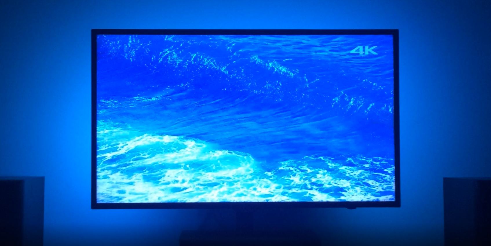
Since I made this, there’s been a lot of change in the media landscape - 4K is now ubiquitous and HDR is becoming mainstream. My software is quickly falling behind, so I expect to revisit this in the near future when I inevitably end up buying a new TV. Based on my experiences there’s a lot of things on my mind about what the next version would look like. Will the Pi, or a more recent version, be able to handle decoding 4K frames? What about 4K HDR frames? Will the capture device still work or would I need to find a new one? How will my software have to change to account for the new picture format?
Actually, that last question is the one I most look forward to solving. Challenge accepted.